Released March 8, 2011
The following is a list of new and updated features in Design Master HVAC 7.0. The major new feature in this release is 3D-BIM compatibility with Revit. The other changes are small improvements to existing features or fixes to bugs reported by customers. If you have any suggestions for features for future releases, you can share them with us on our new wish list.
This release adds 3D-BIM compatibility with Revit, a feature many of our customers have been asking for. It is not a single feature, but multiple smaller features that together allow you to work with architects on 3D-BIM projects. Together, the features put you in the position of being able to offer 3D coordination on every project you do with Design Master HVAC.
The key to 3D coordination is being able to produce a 3D model that can be checked against the other systems in the project. IFC is a vendor-neutral file format that is intended for specifically this type of BIM collaboration. Using this format allows you to design the 3D model in Design Master HVAC and AutoCAD and check it against the architect's model designed in Revit.
You have the option to export the whole project, the current drawing, or a single area from the current drawing.
Mechanical equipment can be modeled in 2D and 3D using the new software. You can model the equipment in 3D as either a cylinder or a box. These 3D elements will be included in the IFC file you export for your architect.

 There are two reasons our new mechanical equipment is limited to simple shapes. The main reason is that the goal of the 3D model is to check for conflicts and interferences, not produce photo-realistic renderings of the project. You need to block out your space for the equipment, nothing more. A 3D box or cylinder accomplishes this goal and allows you to get back to the rest of your design.
The other reason is that computers cannot handle more complex models. The more complicated the model is, the more computer hardware you need to view it. A new process such as 3D coordination needs to be easy to use to be beneficial to the project. If loading the model and checking for collisions is a time-consuming, frustrating task, it won't be done. Keeping our model simple means you and the architect will use it more frequently.
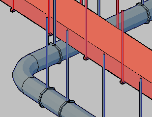
Hangers for ducts can be shown in both 2D and 3D. The hangers will be included in the IFC file you export for your architect. Most project will not require this level of detail for their 3D models, so the default setting for hangers is to be off, but the feature is there when your project needs it.

Elevation labels can be used to document the top and bottom elevations of the ductwork. This was a wishlist request.

Each alignment point area will now have an elevation associated with it. You can use this to stack floors on different drawings appropriately. When the complete IFC model is exported, these elevations are used to put the ductwork and equipment in the right place.
Ductwork can have exterior lining associated with it. This is not currently drawn in 2D, but will be displayed in 3D and included in the IFC file.
Duct Pressure Drop Report: A new report makes it much easier to work with the pressure drop calculations in Design Master HVAC. When you create the report on your drawing, it will highlight the critical path on your drawing. You can use this information to make changes to the ductwork if necessary. In the screen shot below, the critical path is marked by the duct centerlines drawn in magenta.

The report includes the pressure numbers for each section of duct in the critical path. An ID tag links the ducts on the drawing with the rows in the report.

Static Regain Minimum Velocity: You can specify a minimum velocity for your ducts when sizing them using the static regain method. If the starting velocity is not high enough, you can run out of velocity at the ends of the duct runs and require very large ducts. The minimum velocity setting puts a limit on how large the ducts are allowed to be. This setting keeps the duct sizes realistic in these situations.

Critical Zones Highlighted in Ventilation Schedule: The critical zone in the ventilation schedule is highlighted. This is the zone with the largest fraction of outside air required. It is what drives the final corrected outside air value in both the ASHRAE 62 and IMC ventilation calculations. If you want to reduce the corrected outside air required, this is the space that you need to adjust. The typical solution is to increase the supply air to the room, which will lower the outside air fraction.

Reverse Return and Exhaust Ductwork Arrows: Return and exhaust ductwork centerlines can be drawn with their arrows pointing in the direction of airflow rather than pointing towards the diffusers. This settings can be changed in the "Options" command. This was a wishlist request.