Pipe Linetypes
Different linetypes are used to represent different pipe systems (e.g., a single dash for cold water, two dashes for hot, etc.). These dashes appear at certain intervals on each section of pipe so the pipe type is easily identified.
Longer sections do not need dashes to be shown as close together as shorter sections. The
See the General Customization Commands section for more information about how the
To customize pipe linetypes for the current project, go to
Ribbon: Pipe Linetypes
Pulldown Menu:
To customize the pipe linetype standards, go to
Ribbon: Pipe Linetypes
Pulldown Menu:
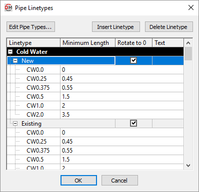
Pipe Linetypes Dialog Box

See the Pipe Types section for more information about pipe types.
-
Press this button to open the Pipe Types dialog box.
-
Press this button to add a new linetype to the list.
-
Press this button to delete the selected linetype from the list.
-
Linetype ☰ The name of the linetype in your CAD program to use for the pipe. If the linetype does not exist on the drawing, it will be loaded automatically from the Linetype file specified in the Options command.
-
Minimum Length The minimum pipe length for which the linetype will be used.
-
☐ Rotate to 0 If this is checked, the text in the Text field will be inserted at a rotation angle of 0. If this is not checked, the text will be parallel to the pipe.
-
Text Text that is inserted on the pipe line when the pipe is inserted.
Hide Pipes Below Ductwork
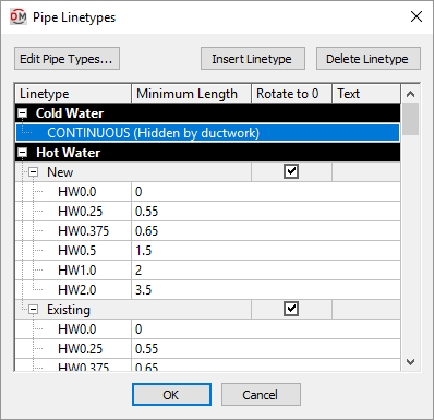
If ☐ Hide Pipes Below Ductwork is checked for a pipe type in the Pipe Types dialog box, you will not able to assign a linetype to that pipe. The pipe will automatically be assigned a CONTINUOUS linetype as shown below.

Distance between text labels in pipes: Sets how frequently inline text is inserted on pipes.
Linetype file: Sets the default linetype used if the linetype specified in this dialog box does not exist in the drawing.