Options
The
See the General Customization Commands section for more information about how the
To edit the options project list, go to
Ribbon: Options
Pulldown Menu:
To edit the options standards list, go to
Ribbon: Options
Pulldown Menu:
Design Master Plumbing Options Dialog Box
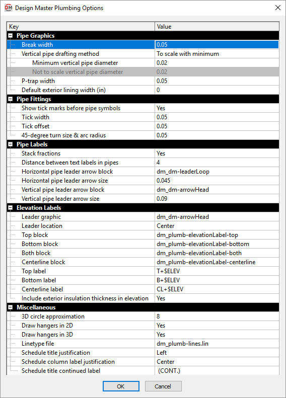
The Design Master Plumbing Options dialog box contains a list of all of the options and their current settings. The options are arranged in groups in the list. The groups are described in the sections below.
Editing a Setting
To edit an option setting, select the Value ☰ in the list and enter a new value.
Press the button to save your changes.
If the change you made to the options does not immediately appear on the drawing, run the Coordinate Drawings and Database command. This command will update the drawing to use the new settings you have specified.
Pipe Graphics
-
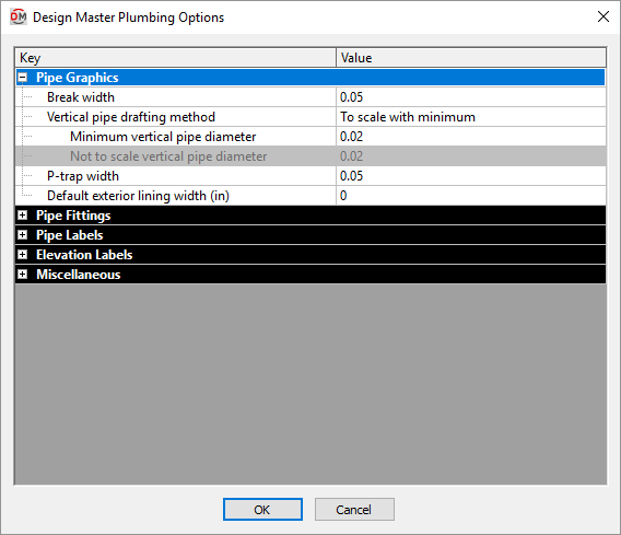
Break width When two pipes cross, a break is automatically inserted on the pipe at a lower elevation. This value determines the width of the break, in inches on the printed page.
-
Vertical pipe drafting method ▾ How vertical pipes are drawn.
- To scale Vertical pipe graphics are inserted at the size indicated. The size is not dependent upon the scale of the drawing. For example, a 3" pipe will be inserted as a 3" circle.
- To scale with minimum Vertical pipe graphics are inserted at the size indicated when above the minimum size specified in the Minimum vertical pipe diameter field. For example, pipes below 2" in diameter will be drawn with a 2" circle to make them easier to see when printed; a 4" pipe will still be inserted as a 4" circle.
- Not to scale Vertical pipe graphics are drawn at the size specified in the Not to scale vertical pipe diameter field, regardless of the diameter of the pipe.
-
Minimum vertical pipe diameter If Vertical pipe drafting method ▾ is set to To scale with minimum, vertical pipes with a diameter below this value will be drawn as a circle with this value as the diameter.
-
Not to scale vertical pipe diameter If Vertical pipe drafting method ▾ is set to Not to scale, vertical pipes will be drawn as a circle with this value as the diameter.
-
P-trap width The width at which p-traps are drawn, in inches on the printed page.
-
Default exterior lining width When a new pipe is created, the exterior insulation is set to this value. See the Common Pipe Information section for more information.
Pipe Fittings
-
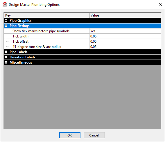
Show tick marks before pipe symbols ▾ Whether tick marks are inserted on the pipe when a pipe symbol is inserted.
-
Tick width The width of tick marks.
-
Tick offset How far from the pipe symbol the tick marks will be inserted.
-
45-degree turn size & arc radius The length of 45-degree angle pipe segments inserted for elbows and tees, and the radius of arc elbows and tees. See the Pipe Types section for more information.
Pipe Labels
-
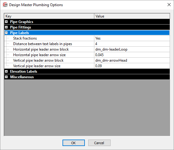
Stack fractions ▾ Whether fractions are displayed as stacked (½") or slashed (1/2").
-
Distance between text labels in pipes The amount of space between inline text on pipes. See the Pipe Linetypes section for more information.
-
Horizontal pipe leader arrow block The block used for leader arrowheads that point to horizontal pipes.
-
Horizontal pipe leader arrow size The length of leader arrowheads that point to horizontal pipes.
-
Vertical pipe leader arrow block The block used for leader arrowheads that point to vertical pipes.
-
Vertical pipe leader arrow size The length of leader arrowheads that point to vertical pipes.
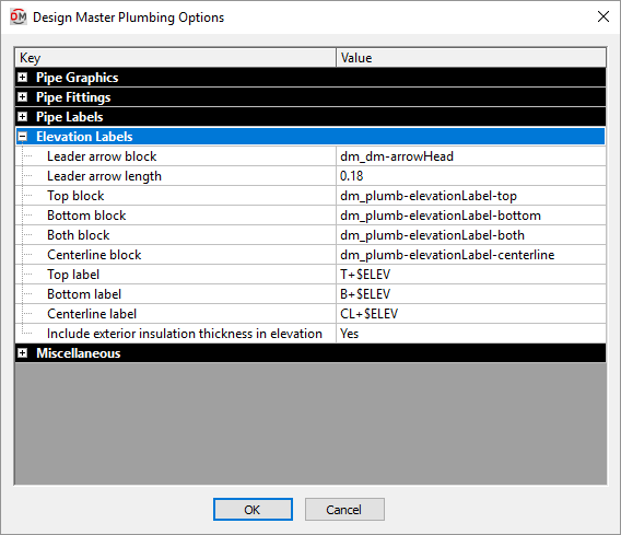
Elevation Labels
-
Leader arrow block The block used for leader arrowheads.
-
Leader arrow length The length of the leader arrowhead.
-
Top block The block used for the elevation label when the Insert Top Elevation Label command is used.
-
Bottom block The block used for the elevation label when the Insert Bottom Elevation Label command is used.
-
Both block The block used for the elevation label when the Insert Top and Bottom Elevation Label command is used.
-
Centerline block The block used for the elevation label when the Insert Centerline Elevation Label command is used.
-
Top label The text that is used to display the top elevation in the label. $ELEV is replaced with the elevation.
-
Bottom label The text that is used to display the top elevation in the label. $ELEV is replaced with the elevation.
-
Centerline label The text that is used to display the top elevation in the label. $ELEV is replaced with the elevation.
-
Include exterior insulation thickness in elevation ▾ Whether the top and bottom elevations include the exterior insulation thickness.
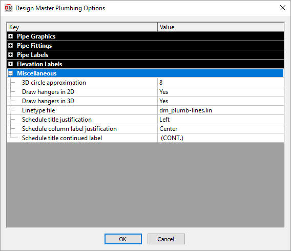
Miscellaneous
-
3D circle approximation Circles are approximated in the 3D model as polygons. This option sets the number of sides of a polygon used to represent a circle. Higher numbers more closely approximate a circle, but greatly increase file size. The minimum number value for this option is 8.
-
Draw hangers in 2D ▾ Whether hangers are drawn in 2D.
-
Draw hangers in 3D ▾ Whether hangers are drawn in 3D. This setting has no impact on the 3D-BIM export commands. It only affects whether they are visible in your CAD program.
-
Linetype File The linetype file for the project. If a new layer is created with a linetype that does not exist in the drawing, it will be loaded from this file.
-
Schedule title justification ▾ The justification for the title at the top of all of the schedules.
- Left The schedule title is justified to the left.
- Center The schedule title is centered.
-
Schedule column label justification ▾ The justification for the label at the top of each column in all of the schedules.
- Left The column labels are justified to the left.
- Center The column labels are centered.
-
Schedule title continued label The text in this option is added to the schedule title when the schedule is broken into multiple sections.
When inserting schedules, there is an option to set a maximum height for the schedule. If the schedule exceeds this height, the schedule is continued in a second section next to the first. The title of the second and following sections is the schedule title plus the text in the Schedule title continued label option.