Creating a Custom Diffuser Callout Block
Creating the Callout Block
-
Open the drawing file that you want to use as the custom diffuser callout. If you do not already have a drawing made for the callout, make the drawing.
-
Scale the entities on the drawing so that everything is the size it should appear when printed on paper. If you want your text 1/10" high, it should be 0.1 units high on the drawing. If you want the callout to be 1" wide, it should be 1.0 units wide on the drawing.
-
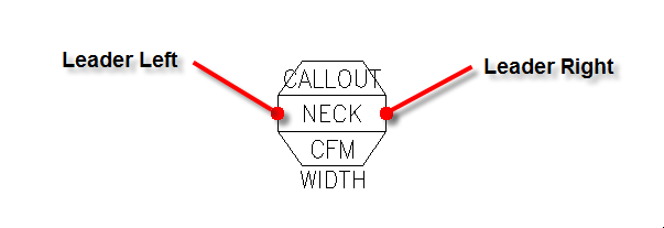
Determine a point where a leader should connect to the left side of the block. Do the same for the right side of the block.
-
Move the block so the left leader point is at 0,0 on the drawing.
-
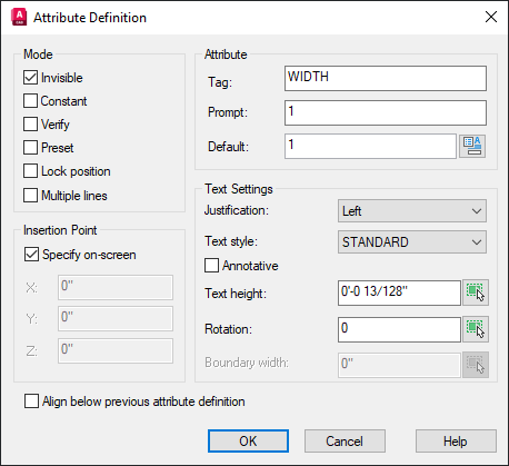
Create an attribute with a Tag set to WIDTH. This attribute will control the location of the right leader point.
-
Measure the distance between the leader points. For the Tag attribute, set Prompt and Default to this width.
-
In the Mode section, check the ☐ Invisible box.
-
Insert the attribute on the drawing. It does not matter where this attribute is located.
-
Use the BASE command and set the base point for the drawing to 0,0.
-
Design Master HVAC will fill in three attributes with information when the block is inserted on the drawing: CFM, CALLOUT, and NECK. Your callout can contain these attributes, but none of them are required.
Set the Tag, Prompt, and Default values to the name of the attribute (either CFM, CALLOUT, or NECK). Set the text style and height on the attribute. These values will not be changed when the callout block is inserted on the drawing. -
Save the drawing file as dm_hvac-diffusercallout.dwg to your HVAC customization folder.
Using the Block in New Projects
To use the callout block in new projects, run the
In the Diffusers section, set the Diffuser callout ▾ option to Custom block.
Using the Block in Existing Projects
To use the callout block in an existing project:
-
Run the
Options->Edit Project List command. -
In the Diffusers section, set the Diffuser callout ▾ option to Custom block.
-
Run the Redefine Block in this Drawing command and select a diffuser callout already on the drawing.
-
Insert a new diffuser on the drawing and confirm that the callout looks correct.
-
Move the callout using the Insert or Move Callout command and make sure the leader points work correctly. Erase this new diffuser if you do not need it in the project.
-
Run the Coordinate Drawings and Database command to update the callouts for diffusers already inserted on the drawing.