Drafting a Meter Center With ElectroBIM
The single-line diagram graphic families provided with ElectroBIM include families for meter centers. This article explains how to use the provided graphic families to draft the meter centers in your projects.
The steps below assume default customization. If the customization files at your company have been modified, the names, locations, and properties of these families may be different.
Inserting the Graphic Families
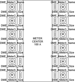
We provide three graphic families to build your meter center: a "middle" graphic for the meter center itself, and left- and right-oriented graphics for the meters.
First, use the Insert Create or Insert Link command to insert the "middle" graphic. It will be listed under the Equipment Type ▾ Other Distribution Equipment as Meter Center. This graphic will connect to other distribution equipment and respond to changes in the electrical model the same way as any other ElectroBIM graphic.

Next, use the Revit Detail Component command, followed by the Load Family command, to insert the left and/or right graphics. Browse to your ElectroBIM customization folder location and select DME-EQU-Meter Center-Left.rfa or DME-EQU-Meter Center-Right.rfa, depending on how you want to configure your meters.
These graphics will not be connected to the electrical model; they exist for informational purposes only, and any changes must be made manually.
Customizing the Meter Center
After inserting the graphics, you will then need to adjust the size, the number of meters, and the labels for each meter. These changes are made using parameters defined in each family.
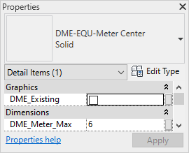
To change the height of each graphic, use the DME_Meter_Max parameter. Set the maximum number of meters for the meter center and the height will adjust accordingly.
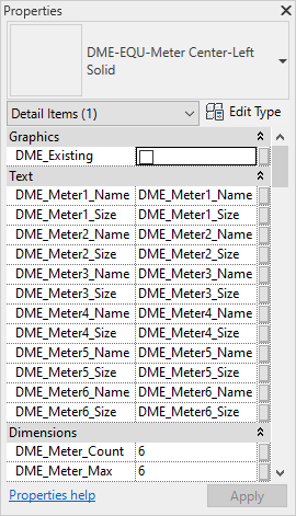
To change the number of meters visible, use the DME_Meter_Count parameter. Each left- and right-oriented family can display 1-6 meters; if you need additional meters, copy and stack the graphics using standard Revit functions.
To change the labels for each meter, use the DME_Meter#_Name and DME_Meter#_Size parameters that correspond to the meter. When you first insert the graphic, each label will list the parameter you need to change.

Circuiting the Meter Center
The left and right meter graphics are not connected to the electrical model and are for informational purposes only.
Downstream connections will connect to the top of the middle meter center family and must be redrawn manually using the Feeder Draw or Feeder Reset command.