Automatic Transfer Switches in Revit
How do I model an automatic transfer switch in Revit? Will it work properly with ElectroBIM?
Automatic transfer switches can be modeled as long as the family and power systems are configured properly using Revit functions:
-
Open the family for the ATS you want to use.
-
Confirm that the family has two connectors, similar to the image below. If not, add a second connector using the Revit Create->
 Electrical Connector command and configure the new connector's properties.
If you had to make changes to the family, load it into the project with the Revit
 Load into Project or
 Load into Project and Close command.
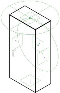
-
Select the ATS and run the Revit Modify | Electrical Equipment->
 Power command. You will be asked to select a connector.
 -
Select either connector from the list and press the button to create the first power circuit.
-
(Optional) Connect the circuit to a panel using the Modify | Electrical Circuits ribbon.
-
Repeat step 4 to create the second power circuit. You may or may not be asked to select a connector.
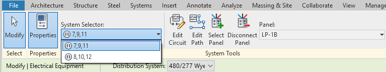
To confirm you've configured the ATS correctly, select the ATS, then go to the Electrical Circuits ribbon (not the Modify | Electrical Circuits ribbon that appears when you create the circuit) and select the System Selector ▾ dropdown menu. You should have two systems to choose from (they may appear as <unnamed> before you connect them to a panel):
Each system can be circuited to a separate upstream distribution equipment. When you run the Panel Edit command, both connections will be shown in the distribution tree:
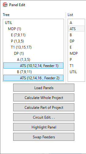
Select either connection to configure the ATS. Feeder and upstream connection settings will be shown for both connections.