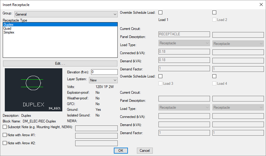
Insert Receptacle
To insert a receptacle on a drawing, go to
Ribbon: Insert Receptacle
Pulldown Menu:
Insert Receptacle Dialog Box

-
Group: ▾ The active receptacle group. The items listed in the Receptacle Type ☰ list are based upon the active receptacle group. The list of groups available is defined in the Receptacle Project Schedule command.
-
Receptacle Type ☰ The type of receptacle to be inserted. The list of receptacles available is defined in the Receptacle Project Schedule command.
The default values for the receptacle are specified based upon the receptacle type you select.
Some of these values cannot be changed in the individual receptacle. To change these values, choose a different receptacle type, or press the button to open the Receptacle Project Schedule dialog box with the selected receptacle type active.
Other values can be overridden in the individual receptacle. To do this, check the box next to the value you want you change. You can then specify the value that will apply to the receptacles you will insert on the drawing.
-
Elevation: The elevation of the receptacle. See the Elevation section for more information.
-
Layer System: ▾ See the Layer System section for more information.
-
☐ Override Schedule Load: Check these boxes to override the load defined in the schedule. If this box is checked, the load fields below it will be enabled and can be changed.
See the Common Receptacle Information section for more information about the other values in this dialog box.
Inserting the Receptacle on the Drawing
To insert a receptacle on the drawing, press the button. The settings specified in the dialog box will be used for the inserted receptacle. You will be prompted to identify where on the drawing the receptacle is to be inserted.
Specify insertion point:
You will then be prompted for the rotation angle. If the receptacle block is not able to be rotated, this prompt will be skipped.
Specify rotation angle <0>:
If there are any notes included with the receptacle, you will then be prompted to insert the notes on the drawing. See the Inserting Notes and Leaders on the Drawing section for more information about inserting the notes.
You will then be prompted to insert another receptacle of the same type. Continue to insert receptacles, or press ENTER to finish the command.
Receptacles options: Sets the text of the label inserted on the drawing with the receptacle if Explosion-proof, Weather-proof, GFCI, Ground, or Isolated Ground is set to Yes.
Insert 3D blocks on drawing: Sets whether a 3D block is inserted on the drawing along with the 2D block.