Electrode Configurations for Arc-Flash Calculations
In order to calculate arc-flash for a piece of distribution equipment, you must set its electrode configuration as described in IEEE Std 1584-2018 Table 9.
This article illustrates each electrode configuration so you can determine the appropriate option for your distribution equipment.
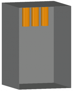
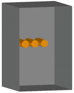
VCB
These images show examples of a Vertical conductors or electrodes inside a metal box or enclosure configuration.
The conductors extend from the top, left, or right of a metal box or enclosure and do not discharge in the direction of the operator.
This configuration typically results in lower incident energy values than other configurations except for VOA.
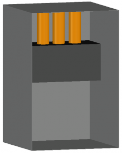
VCBB
This image shows an example of a Vertical conductors or electrodes terminated in an insulating barrier inside a metal box or enclosure configuration.
The conductors extend from the top, left, or right of a metal box or enclosure and terminate in an insulating barrier.
This configuration typically results in higher incident energy values than other configurations except for HCB.

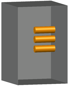
HCB
This image shows an example of a Horizontal conductors or electrodes inside a metal box or enclosure configuration.
The conductors extend in the direction of the operator from the back of a metal box or enclosure.
This configuration typically results in the highest incident energy values.
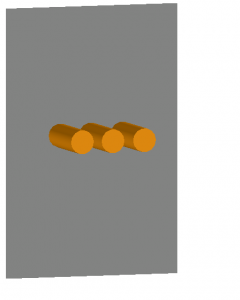
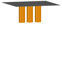
VOA
These images show examples of a Vertical conductors or electrodes in open air configuration.
The conductors extend from the top, left, or right, do not discharge in the direction of the operator, and are not enclosed.
This configuration typically results in the lowest incident energy values.

HOA
This image shows an example of a Horizontal conductors or electrodes in open air configuration.
The conductors extend in the direction of the operator and are not enclosed.
This configuration typically results in higher incident energy values than VOA and VCB, but lower than VCBB and HCB.